這是我自己讀OPERATING SYSTEM CONCEPTS (6th Edition)的筆記,本來讀的進度很緩慢,直到有一天在網路上看到冼鏡光老師分享上課的slide(OS第7版),唸起OS就愈來有趣啦。
筆記的章節是依OS第6版整理的,圖片則都是從冼鏡光老師的slide貼上來的,感謝冼老師無私的分享,讓我有機會一窺OS的奧妙。
(如有著作權相關問題,請惠予通知)
筆記的章節是依OS第6版整理的,圖片則都是從冼鏡光老師的slide貼上來的,感謝冼老師無私的分享,讓我有機會一窺OS的奧妙。
(如有著作權相關問題,請惠予通知)
13. I/O Systems
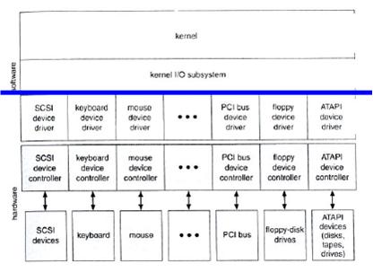
- The kernel of an OS is structured to use device-driver modules; the device drivers present a uniform device-access interface to the I/O subsystem.
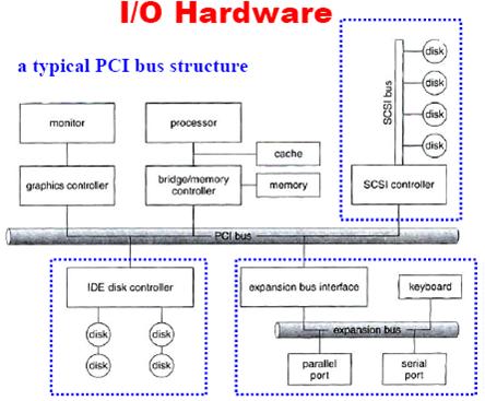
- A daisy chain usually operates as a bus.
- How do the processor and controller communicate?
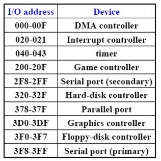
- Use the controller with special I/O instructions: a controller usually has a few registers (e.g., status, control, data-in and data-out).
- Use memory-mapped I/O.
- Or, a combination of both.
- Memory-Mapped I/O
- Each controller has a few registers that are used for communicating with the CPU.
- If these registers are part of the regular memory address space, it is called memory-mapped I/O.
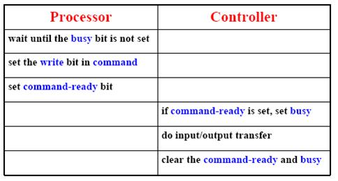
13.3 Application I/O Interface13.2.1 Polling
- The status register has two bits, busy and command-ready.
- In many computer architecture, three CPU-instruction cycles are sufficient to poll a device: read a device register, logical-and to extract a status bit, and branch if not zero.
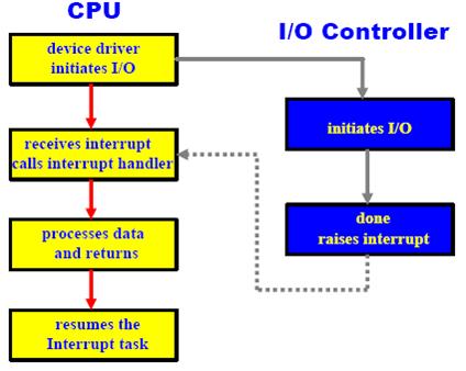
13.2.2 Interrupts
- The CPU hardware has a wire called the interrupt-request line that the CPU senses after executing every instruction. When the CPU detects that a controller has asserted a signal on the interrupt request line, the CPU saves a small amount of state, such as the current value of the instruction pointer, and jump to the interrupt-handler routine at a fixed address in memory.
- The interrupt handler determines the cause of the interrupt, performs the necessary processing, and executes a return from interrupt instruction to return the CPU to execution state prior to the interrupt.
- We say that the device controller raises an interrupt by asserting a signal on the interrupt request line, the CPU catches the interrupt and dispatches to the interrupt handler, and the handler clears the interrupt by servicing the device.
13.2.3 Direct Memory Access
- CPU and interrupt-controller hardware provide three features:
- The ability to defer interrupt handling during critical processing.
- An efficient way to dispatch to the proper interrupt handler for a device, without first polling all the devices to see which one raised the interrupt.
- Multilevel interrupts, so that the OS can distinguish between high- and low-priority interrupts.
- Most CPUs have two interrupt request line:
- One is the nonmaskable interrupt, which is reserved for events such as unrecoverable memory errors.
- The second interrupt line is maskable: It can be turned off by the CPU before the execution of critical instruction sequences that must not be interrupted.
- The purpose of a vectored interrupt mechanism (interrupt vector) is to reduce the need for a single interrupt handler to search all possible sources of interrupts to determine which one needs service.
- Interrupt chaining: each element in the interrupt vector pointes to the head of a list of interrupt handlers.
- Interrupt priority levels: a mechanism enables the CPU to defer the handling of low-priority interrupts without masking off all interrupts, and makes it possible for a high-priority interrupt to preempt the execution of a low-priority interrupt.
- The interrupt mechanism is also used to handle a wide variety of exceptions, such as dividing by zero, accessing a protected or nonexistent memory address, or attempting to execute a privileged instruction from user mode.
- A system call is a function called by an application to invoke a kernel service. The system call checks the arguments given by the application, builds a data structure to convey the arguments to the kernel, and then executes a special instruction called a software interrupt (or a trap).
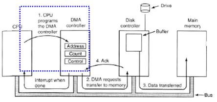
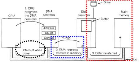
- For large volume data transfer, most systems use direct memory access to avoid burdening the CPU.
- The CPU gives the controller (1) disk address, (2) memory address for storing the block, and (3) a byte count. Then the CPU goes back to work.
- DMA requests data transfer to memory.
- The disk controller copies the information into the address provided by the CPU, byte-by-byte, until the counter becomes 0, at which time an interrupt is generated.
- Handshaking between the DMA controller and the device controller is performed via a pair of wires called DMA-request and DMA-acknowledge.
- The device controller places a signal on the DMA-request wire when a word of data is available for transfer.
- This signal causes the DMA controller to seize the memory bus, to place the desired address on the memory-address wires, and to place a signal on the DMA-acknowledge wire.
- When the device controller receives the DMA-acknowledge signal, it transfers the word of data to memory, and removes the DMA-request signal.
- The purpose of the device-driver layer is to hide the differences among device controllers from the I/O subsystem of the kernel, much as the I/O system calls encapsulate the behavior of devices in a few generic classes that hide hardware differences from applications.
- Character stream: a character stream device transfers byte one by one (e.g., modem).
- Block: a block device transfers a block of bytes as a unit (e.g., disk).
- Others: clocks, memory-mapped screens and so on.
- Not all devices may be recognized by an OS. Thus, device drivers are needed.
- Many OS also have an escape (or back-door) that transparently passes arbitrary commands from an application to device driver.
- The ioctl () system call has three arguments:
- The first is a file descriptor that connects the application to the driver by referring to a hardware device managed by that driver.
- The second is an integer that selects one of the commands implemented in the driver.
- The third is a pointer to an arbitrary data structure in memory, thus enabling the application and driver to communicate any necessary control information or data.
13.3.1 Block and Character Devices13.4 Kernel I/O Subsystem13.3.2 Network Devices
- Application normally access block or character devices through a file-system interface.
13.3.3 Clock and Timers13.3.4 Blocking and Nonblocking I/O
- The hardware to measure elapsed time and to trigger operations is called a programmable interval timer.
- When an application issues a blocking system call, the execution of the application is suspended. The application is moved from the OS’ run queue to a wait queue. After the system call completes, the application is moved back to the run queue, where it is eligible to resume execution, at which time it will receive the values returned by the system call.
- The difference between nonblocking and asynchronous system call is that a nonblocking read () returns immediately with whatever data are available. The asynchronous read () call requests a transfer that will be performed in its entirety, but that will complete at some future time.
- Build on top of hardware and device drivers, the kernel usually provide many I/O services.
- Another service is name translation, to make the connection between hardware devices and the symbolic file names used by applications.
13.4.1 I/O Scheduling13.5 Transforming I/O to Hardware Operations13.4.2 Buffering
- OS developers implement scheduling by maintaining a queue of requests for each device.
- A buffer is a memory area that stores data while they are transferred between two devices or between a device and an application.
- Major reasons of using buffers
- To cope with a speed mismatch between the producer and consumer of a data stream.
- To adapt between devices that have different data-transfer sizes.
- Efficiency
- Copy semantics. What if there is no buffer and a process runs so fast that overwrites its previous write? The content on the disk becomes incorrect. The use of buffers overcomes this problem.
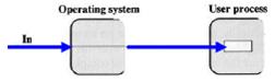
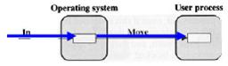
- No buffer: The user process must wait until data transfer completes
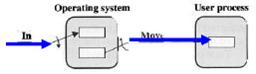
- One buffer: While the user process is running, next data transfer may begin.
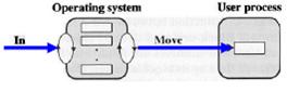
- Double buffer: while the user process is processing he first buffer, data transfer can be performed on the second.
- Multiple buffers: very efficient
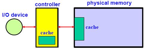
13.4.3 Caching
- Just like a cache memory between the faster CPU and slower physical memory, a cache (i.e., disk cache) may be used between the faster physical memory and slower I/O devices.
- Not that buffering and caching are different things.
13.4.4 Spooling and Device Reservation13.4.5 Error Handling
- A spool is a buffer that holds output for a device, such as a printer, that cannot accept interleaved data streams.
13.4.6 Kernel Data Structures
- In UNIX, the device name space is incorporated in the regular file-system name space.
- When UNIX looks up device name in the file-system directory structures, instead of finding an inode number, UNIX finds a <major, minor> device number. The major device number identifies a device driver that should be called to handle I/O to this device. The minor device number is passed to the device driver to index into a device table. The corresponding device-table entry gives the port address or the memory-mapped address of the device controller.
- STREAMS enables an application to assemble pipelines of driver code dynamically.
- A stream is a full-duplex connection between a device driver and a user-level process. It consists of a stream head that interfaces with the user process, a driver end that controls the device, and zero or more stream modules between them.
- Modules provide the functionality of STREAMS processing and they are pushed onto a stream using the ioctl () system call.
- STREAMS provides a framework to a modular and incremental approach to writing device drivers and network protocols.